

We all have seen the mounting of solar panels in a structure. During the design, the loading and failure conditions must be identified so that they can be designed to sustain all the loads during their service life. In general, a structure is designed for various loading conditions like Seismic load, Load of self-weight, wind load, etc. Here we will discuss the design calculation in case of wind load. Before proceeding further let us see how a structure can fail due to wind load.
Generally, the following phenomena with the structure occur which causes a structure to fail:
- Swaying or oscillating: this phenomenon happens due to the lateral forces caused by wind.
- Shear: sometimes wind induces a force that may move the complete structure horizontally. This is known as shear.
- Torsion: Wind also induces a twisting force on it and hence failure due to torsion.
In order to prevent a structure from failing due to wind, it is important to ensure that the structure is properly designed and constructed to withstand the forces exerted on it by the wind. This may involve using materials and design techniques that are able to withstand wind loads, as well as properly securing the structure to the ground.
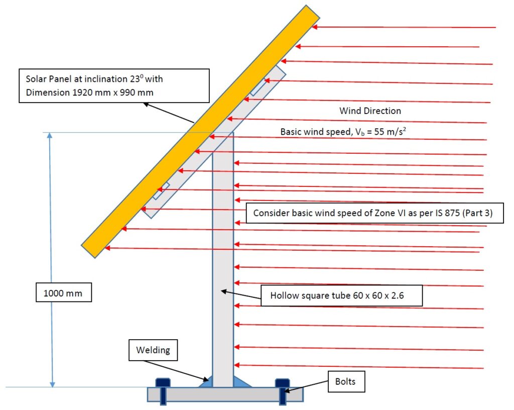
Figure: The solar panel mounted on the Structure
let’s have a look at the assembly of the solar panel structure as shown in the figure. The parts that we have to look out for or the parts that may fail due to the phenomena mentioned above are as
- Failure of Bolts
- Failure of Square tube
- Welding failure
Design Calculation for Square tube and Weld failure
Pwind , Pressure due to wind = 0.6 x V2
V = Deign Velocity
V= K1 K2 K3 Vb
Vb = Basic wind speed which is taken as 55 m/s for Zone VI as per IS: 875 Part 3
K1 = Risk coefficient or Probability factor
= 1, for Vb = 55 m/s as per table 2 of IS:875
K2 = Terrain Height and structure size factor
= 1, as per table 3 of IS: 875
K3 = Topography factor, taken as unity if the slope of the ground is < 30
So, Pressure due to wind can be calculated as
Pwind = 0.6 x V2 N/m2 = 0.001815 N/mm2
Effective force on Panel (FP) and support (Fs) is Calculated as
FP = 1920 x 990 x sin 230 x 0.001815 = 1348 N
Fs = 60 x 1000 x 0.001815 = 108.9 N
Moment Generated at the Base due to the above-calculated force
M = 1348 x 1000 + 108.9 x 500 = 1402450 Nmm
Here, we have considered a Square tube for support of Size 60 x 60 x 2.6 having section Modulus equivalent to 10.44 x 103 mm3
As the failure of Support will take place due to Bending
Sb, Bending stress developed in the tube =(Moment Generated/Section Modulus) = 134.33 N/mm2
Considering a Safety factor of 1.5 and the Material, having a Yield Strength of 250 Mpa, we can say that the Square tube taken here can sustain the wind Load without Failure.
Failure of welding will take place due to a Direct shear force of 1456.9 N and Bending Stress on welding due to a moment of 1402450 Nmm, generated at the base
Direct Shear Stress, Ss = (Shear Force/Area of the weld)
Area of Weld = t x (2 x 60 + 2 x 60)
t = Throat thickness = 0.707s
s = weld size
Maximum Shearing load capacity of weld = 0.5 x 250 = 125 Mpa
Maximum Permissible shearing stress considering a safety factor of 1.5 is 83.33 Mpa
The size of the weld, s can be calculated as
Ss =(1456.9/0.707s x 4 x 60) = (8.58/s) N/mm2
Section Modulus of the weld = 3393.6 x s mm3
Sb , Bending stress developed in the Weld =(Moment Generated/Section Modulus) = (413.26 / s) N/mm2
Maximum Shear Stress, TMax = 0.5 x [(Sb)2 + 4(Ss)2]0.5
83.33 = 0.5 x [(Sb)2 + 4(Ss)2]0.5
s = 2.48 mm
The size of the weld to be done, at the base, to sustain the wind load is 3 mm.
The calculation for foundation Bolts
Failure of the bolts will take place due to the swaying or oscillation of the structure due to lateral force.
The Bolts will be under tension while resisting the structure during oscillation and under shear due to wind lateral load.
let’s calculate the required size of the Bolts.

The bending moment generated due to oscillation = 1402450 kg mm (Calculated above)
This moment will generate tensile force calculated as
2F (252+3752) = 1402450
F = 4.96 kg/mm
Maximum Tensile Force, Fmax. = 4.96 x 375= 1860 kg
If the Size of the bolt = M16 (PC 4.6) having core dia. 14mm
Tensile stress, Ts =1860 x 4/3.14 x 142 = 12.08kg/mm2
Shear force per bolt= (1348+108.9)/4= 364.225 kg
Shear stress, Ss = 364.225 x 4/3.14 x 142 = 2.36 Kg /mm2
This way we can calculate the size of the solar panel structure, welds, and Bolts.
Considering allowable tensile stress for Bolts of property class 4.6, 160 Kg /mm2, the required size of the Bolts is well sufficient to withstand the seismic load.